skip to main |
skip to sidebar
Since the early part of the 20th century, engine, vehicle and aircraft manufacturers have developed means to test the power output of their products....
By far the best known, in the British sphere of things anyhow, is the firm Heenan and Froude Ltd. of Worcester, UK.
Reading through the English motorcycling press one sees reference to the DPX water brakes from Heenan & Froude.
So I've scratched around my stuff and come up with enough to run a generalised look at the dynomometer.
Including notes from Phil Irving's Autobiography and his little black notebooks from his time at Veloce Ltd.
So left click on any images to enlarge them.....
PEI on his return to Australia after years in the UK spent time at Repco Ltd., a company that developed an engine for Jack Brabham's successful attempts at the F1 automotive world championship title.
He won the title three times and third time used the Repco-Brabham and the cylinder head was developed by PEI and as it so happens the Heenan & Froude dyno he used for the testing has been given to the National Motor Racing Museum of Australia in Bathurst, NSW.
It is pictured below...
Veloce Ltd built a new test house at their factory and inside it there were several Heenan & Froude DPX dynos installed. Stanley woods was invited to open it and is pictured below. Design engineer and race shop supremo, Harold Willis is pictured in the white dust coat.
Inside, Stanley simulates operating the engine controls for a TT engine on test while Harold Willis and Percy Goodman, the Veloce managing director look on.
Race mechanic Tommy Mutton tests a Mk.8 KTT, a production racer engine sold to the public from 1939-1951.
Tommy Mutton and development engineer Charles Udall with a 1947 350 SOHC TT Velocette engine on test.
PEI developed the military MAC and unused MSS engines during WW2 at Velocette.Below is his results from a test of a 350 MAF engine.
From one of PEIs little black notebooks...the data is the "pull" of the brake or dyno which, via a simple calculation, knowing the RPM you get the BHP developed.
PEI did an article for " MotorCycling" on Jack Williams development of the postwar 7R AJS engine.
During 1939 a contributor,to "The MotorCycle" using the Nome-de plume of "Ubique" did an article on the dynamometer...the Heenan & Froude DPX...
The Owen Organisation were involved in the development of the BRM racing car engine used in F1 world championship GPs.
Below is a race car in 1965 or 1966 on a rolling road dynamometer which gives the BHP developed at the rear wheels.
They also used Heenan & Froude engine dynamometers as illustrated in the advertisement...
Note in the above photograph, there is no attempt to silence the exhaust into a large chamber. The brake operator, even with earmuffs must have had a headache at the end of the day.
Contrast this with the pre-war Velocette test house where the exhaust pipe goes into a large chamber allowing the operator some relief from the noise...
Even if we consider it "good" noise...
A BMW Rennsport 500cc twin engine used in racing sidecars in the GP races and engine dyno in the workshop of Krauser in Munchen, Germany. Photo taken by DQ in 1974.
Above a 500 speedway JAP engine on test late 1946.
Below, photo taken at JAP the proprietary engine maker in London, prewar...
From "The MotorCycle", January 7th 1937....
From the French motorcycle magazine "Moto revue", #1375, 25 Jan.1958,
a 175cc Terrot motorcycle engine on test. The gave about 10.6 CV or bhp.
And finally...what happens if you make a model engine and need to test it?
This article comes from a paper clipping, it is pre-war and likely 1936...
From an article in "The MotorCycle" dated 4th Feb.1960, pages 138,139 the two photos above show a sectioned Froude water dynomometer and a Triumph Thunderbird engine on test on a water dyno.
Chev 6 cylinder OHV engine on test, Castrol, 1957
Velocette engine on a dynomometer test bench at Hall Green...probably a Venom engine.
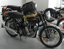
Recently...Dec.2013, I was sent some interesting Vincent factory photographs and the two following are of Vincent engines on their dynomometer, probably in 1948-49...my friend Ian Brock comments...
"Obviously in the Fisher's Green Works. Also known as the No.2 Factory. It was in the process
of being demolished when I saw it during my first visit to England in
1979."
The 1960's and into the 1970's in Britain saw an upsurge of interest in "go fast" items or "go fast goodies" as the Motorcycle press labeled it.
So lets look into the 5th May 1966 edition of "The MotorCycle" and browse through some dozen or so pages with offerings from motorcycle dealers and small outfits that concentrated on items for one make.....
Left click on the images to enlarge them....