This would have to be on the “Must Get” list of Velo people interested in the racing efforts of the Velocette factory and riders of KTTs amongst other things.
It is the insight into the racing career of a private owner, a rider who really never quite made the top ranks in the sport, but who in essence are the “backbone” of the sport, for without them filling the grids at the myriad of meetings around the world, there would be no motorcycle racing.
Apart from his own experiences, Higgins writes about the other riders of the major race meetings of his time with details of each race meeting,with lap times, some photos and who won what.
It certainly compliments the few other books written of the era, results wise.
Les Higgins wrote the book and it was published in 1948 by G.T.Foulis & Co. Ltd, of London, UK.
As he relates….”This is not the story of the successes of a works rider but that of a private owner, who went a racing for the sheer joy of it.”
He was a schoolboy in 1924 and first saw motor racing along the promenade during the Herne Bay speed trials- bitten by the bug, he purchased , in 1929, a new OHC Velo to ride on the road and plan his entry into racing. He purchased used racers during the 1930s ...a KTT Mk.4 and then a Mk.5, supporting his “habit” from his weekly pay packet of 57 shillings and finally bought a new Mk.7 KTT in 1938, although this meant he had to enter the IOM TT to gain delivery of the bike, something he hadn’t planned and he was dubious over it.
He raced, largely without major success but eventually obtained some support from a motorcycle dealer in 1947, one George Bryant known as “the Rider Agent”.
What happened to Les? I wrote enquiring of him in 1972 and his son replied to the effect that he was killed in a car accident around this time, returning from one of his several trips to northern Scotland to study bird life, another of his passions.
He also wrote several other motorcycle oriented books, and "Britains Racing Motorcycles" is one of them, also published by Foulis in 1952.
Quite hard to obtain and expect to pay around £25 ( around A$70) for a copy and it probably won't have the dust cover as illustrated.
Occasionally I see them offered on Ebay.
Les is pictured on his Mk.7 KTT, although this is at the 1939 IOM TT races in which he finished 29th in the Junior TT at 73.39mph average speed, with a fastest lap of 30m 12s.
Glancing through the ACU Stewards report of the race reveals he won a bronze replica and £20.... to get this the report says....
"To the entrant of every motorcycle other than the first six to be placed, that completes the course outside 9-8ths but within 6-5ths of the winners time: A Bronze Replica of the Tourist Trophy and £20"
The print is an S.R.Keig print code..1939/A9.... I believe Bill Snelling in the IOM, trading as Amuree publications, email amulree@mcb.net. has the rights to S.R.Keig's photographic archives.
Talking of these archives...when in the IOM for the TT in 1974, I haunted S.R.Keig's shop in Circular Road, Douglas...they let me look at all their glass plate negatives, using these up to about 1939. They were well organised, but little known, although they had a catalogue of their negatives from which I had copies made of all the Velocettes up to about 1951.....
Gold dust now.....
The other shows Les , again in 1939 from a small sepia print I acquired years back and judging by his leather coat blown open, it was quite windy...
Left click on images to enlarge....
Thursday, July 31, 2008
Wednesday, July 30, 2008
An introduction to Allan Schafer.....
Those of you reading my blog will have delighted in the photographs and letters written to Allan Schafer in reply to his correspondence in the 1930s....
I'd like to share a couple of photos of Allan as a younger man around this time.....
Allan is shown on his 1940 MAC 348cc Velocette, likely in the Grafton area of NSW where Allan lived all his life, running the family motorcycle, then later bicycle business. He was an excellent tennis player and was involved in tennis at a State level.
A prolific letter writer, he wrote to many famous riders, both in Australia and overseas, receiving delightful letters, now so historic, in reply, usually with an autographed photograph.
These have proved invaluable to historians today and Jim Scaysbrook, editor of "Old Bike Australasia" is keen to utilise them.
Not heard of Old Bike Australasia? A new addition to newsagents in the Historic/Classic literature field and now published bi-monthly, for details check out http://www.bandt.com.au/view_media.asp?mediaid=150150
I'd corresponded with Allan sporadically over the years in my Velocette research and met him several times and was delighted when he invited me to become custodian of his collection, sometime in the 1990s....this blog has to be an obvious solution to sharing his treasures with those interested.
The other photograph, also taken in 1940, at the Easter Australian GP races at Bathurst, NSW, is of Allan watching Tommy Jemison, a sponsored rider from the NSW Velocette Distributor, P & R Williams of Sydney, fettling his Mk.8 KTT.
Few Mk.8 KTTs came into Sydney in 1939, prior to the outbreak of WW2 and is likely to have been either of the two last Mk.8's made in 1939, engine numbers, KTT850 and KTT851 ( I owned the frame of KTT851, serial number SF55 for many years with another KTT engine in it..."nice piece of kit.." as they say).
Left click on the images to enlarge...
Sunday, July 27, 2008
Electric starters on Velocettes......
Electric starters years back were not really able to be easily adapted to English motorcycles...but with the changes in battery technology, Japaneses auto starter motors being ever smaller, and I guess the aging in riders who enjoy these motorcycles, the electric starter is a viable alternative to not riding at all.
Seen on the outskirts to Perth, Western Australia.
Paul Zell's second version.
Paul Zell of California, had two versions of electric starters on two of this Velos. The latter is illustrated, with chain drive and a neatly placed alternator on the engine crankshaft...sourced from a Japanese motorcycle wrecker. Paul had coil ignition with no advance until about 300rpm, so there would be no engine kickback which he found had done damage on his other setup.
Cory Padura from Canada came up with the last illustrated...he utilised a heron "v' type drive belt arrangement and a starter from a Honda Accord car from memory with a gear drive arrangement, illustrated. Cory also made provision for an alternator on the crankshaft.The belt is a really good idea, using the offset V rather than the straight teeth which require a belt that won't fit into the narrow Velo primary chaincase.
Seen on the outskirts to Perth, Western Australia.
I've selected four versions that I 've seen in the last couple of years, two eminating in the USA and two in Australia.
The US versions seem to me to be the more suited to our needs, as they encompass alternators and even belt drives in their setup so that the final package is good.
Bryan Cave's starter operating into the kick start housing.
I'll start with the two Australian ones, which seem to be an early development of the US versions, although I'm pretty sure their existence was unknown to each other.
Travelling to the Cape to Cape Velocette rally in Western Australia in 2003 from the Eastern States, as we approached Perth, we were greeted by a local Velo rider, who'd ridden to meet us...sadly his name escapes me, but I quickly noted his mid 1950s Venom had an electric starter on it.... he had no generator and just charged the battery nightly, with some 30 starts in the "package"...an interesting solution.
At the 2004 Australian Velocette Owners Club National Rally at Bright in Victoria, Bryan Cave had his version of an electric start, which curiously drove into the gearbox via the kick start housing.
I never really questioned Bryan over the why's and wherefores of it....
Onto the USA......
Paul Zell's second version.
Paul Zell of California, had two versions of electric starters on two of this Velos. The latter is illustrated, with chain drive and a neatly placed alternator on the engine crankshaft...sourced from a Japanese motorcycle wrecker. Paul had coil ignition with no advance until about 300rpm, so there would be no engine kickback which he found had done damage on his other setup.
Cory Padura from Canada came up with the last illustrated...he utilised a heron "v' type drive belt arrangement and a starter from a Honda Accord car from memory with a gear drive arrangement, illustrated. Cory also made provision for an alternator on the crankshaft.The belt is a really good idea, using the offset V rather than the straight teeth which require a belt that won't fit into the narrow Velo primary chaincase.
Cory's set up will and carries the load. The belts are freely available from GoodYear.
All appear to do the job for the owners and Cory has produced small quantities for sale to those who were prepared to wait.
Thursday, July 24, 2008
Ernst Henne… record breaking with BMW supercharged motorcycles….
Another selection from Allan Schafer's literature collection, now in my custody....
Allan Schafer of Grafton, a town in northern NSW, Australia as a young man was a prolific letter writer to overseas motorcycling "greats", this one is a reply to his letter together with an autographed photo. Allan wrote to Ernst Henne in Germany in 1936. It is interesting to note the swastika on the franking mark on the envelope that brought the reply.
Former BMW works driver and rider Ernst Henne died on Sunday May 24, 2005 at the age of 101.
In the 1920s and 1930s, he achieved endless victories, championships and speed records on two wheels; he was also on the list of winners of many international races on four wheels.`
Ernst Jakob Henne was born on 22.02.1904 as the fourth child of a master saddler in Weiler near Wangen im Allgäu. In 1919 he started his apprenticeship to become a motor vehicle mechanic, before becoming an independent motor cycle mechanic. In July 1923, he was amongst the starters in a motorcycle race in Mühldorf, almost by accident, and immediately achieved third place in his class on his first time out. In autumn 1925, he made his first major international appearance in the Monza Grand Prix, coming sixth in the 350 cc class.`
After this success, he signed a contract with BMW as a works rider. In 1926, he also became the official representative of BMW Motorcycles, and also became one of the original BMW automobile representatives. Ernst Henne achieved his first victory for BMW in May 1926 in the "Karlsruher Wildparkrennen". He came first in the Eiffel Race in the same year, thus also winning the German Championship, which was still decided in one race in those days.`
At the end of the 1920s, he was regarded as one of the best, most versatile motorcyclists in Germany.
He took part in the International Six Day Trial at the beginning of the 1930sand in 1933, 1934 and 1935 he won the team event with the national team, which was in actual fact a pure BMW team.`
Once the BMW Board of Management had given the go-ahead to attempt land speed record attempts, a super-charged engine, which had already been started, was fully developed. The frame was made in Henne's own workshop.`
On 19 September 1929, Henne chased the record for the first time with a 750 cc super-charged BMW, breaking eight world records that day. Not all of them were officially recognized, but the most spectacular stayed: at a speed of over 216 km/h, Ernst Henne was the fastest motorcycle rider in the world.
National pride was a big thing in those days…guess it still is today… riders from Great Britain also challenged for the World’s fastest on two wheels. Joe Wright OEC, Zenith, Eric Fernihough all made attempts and held records for periods of time.
In 1932, Henne reached 246 km/h in Hungary; on the new motorway in Frankfurt, he reached 256 km/h in 1935, and just one year later he achieved 272 km/h on a fully enclosed motorcycle. Because of its characteristic shape, the driver and his motorcycle soon became popularly known as "Henne and his egg".`
In 1936, he drove the first BMW 328 prototype in the Eiffel Race and not only won the normally aspirated 2 litre class , but also achieved the best time of all the sports cars that had started with an average speed of 101.5 km/h .
With the BMW 328, he then went on to win the Belgian Grand Prix des Frontières in Chimay and the Bucharest Grand Prix.`
On the morning of 28 November 1937, Henne finally reached the high point of his career achieving an officially certified speed of 279 km with the "Egg", reaching 280 km/h on his return.
Ernst Henne then retired from record breaking, but his record remained unbroken until 1951.
After the Second World War, Henne developed a contract workshop for Mercedes-Benz vehicles and became one of the largest dealerships in Germany. His company became part of DaimlerChrysler AG in 1997. In 1991, he also founded, with a considerable proportion of his assets, the Ernst-Jakob-Henne Foundation. The aim of the foundation is to support people who are innocent victims of suffering.
Ernst Henne, who withdrew increasingly from public life in latter years, lived with his second wife in the Canary Islands from 1996 on until his death.
Acknowledgement is made to the BMW motorcycle Owners of America for information on Henne’s life.
Left click on images to enlarge.
Tuesday, July 22, 2008
Pictures from my Archive… a frequent dip into photographs that I want to share with you….
Continuing with another selection from Allan Schafer's literature collection, now in my custody....
Allan Schafer of Grafton, a town in northern NSW, Australia as a young man was a prolific letter writer to overseas motorcycling "greats". This one is a reply to his letter together with an autographed photo, from George Brough a flamboyant character in English motorcycling, whose motorcycle business did not survive after WW2.
Perhaps his motorcycles were better known in the hands of T.E.Lawrence..."Lawrence of Arabia" who was reputed to have owned seven and was killed on one. An earlier blog featured Eric Fernihough who also used Brough Superior motorcycles.
Strangly the name Brough Superior has passed through various hands since then and is in the news again with the report that the business, British Only Austria, has purchased the naming rights etc with the intention of re-manufacturing Brough Superiors.
Time will tell whether it is just another pipe dream.
Left click on images to enlarge...
Sunday, July 20, 2008
Pictures from my Archive… a frequent dip into photographs that I want to share with you….
Continuing with another selection from Allan Schafer's literature collection, now in my custody....
Allan Schafer of Grafton, a town in northern NSW, Australia
Illustrated above, Jimmy during the 1937 Dutch TT with team manager Joe Craig and team mates Freddie Frith and J.H "crasher" White.
as a young man was a prolific letter writer to overseas motorcycling "greats", this one is a reply to his letter together with an several photos from Jimmy Guthrie, the great Norton factory rider on the mid 1930s, tragically killed in Germany on 8th August 1937.
Several of the envelopes containing the letter from Guthrie to Allan are illustrated and if you are observant, you'll notice the stamps contain the head of the English king, George 5th and the other the head of Edward 8th.
The interest is the Edward the 8th stamp, as King George 5th died on 20th January 1936, and his eldest son became king as Edward 8th. The dead king's stamps were continued to be used until new dies were stuck for the issue of Edward 8th stamps...then a constitutional crisis developed in England, as the new king announced he was to marry Wallace Simpson, the divorced American socialite... Edward abdicated in favour of his brother, George 6th and so relatively few stamps were produced as the dies were defaced and only a hand full of coins produced, believed to be mint sets.... The stamp illustrated is one of those few.
Possibly the last photograph of Jimmy Guthrie alive...taken in the pits during practice for the 1937 German GP...Mildred Woods, wife of Stanley Woods, Jimmy Guthrie and team-mate Freddie Frith.
Allan Schafer of Grafton, a town in northern NSW, Australia
Illustrated above, Jimmy during the 1937 Dutch TT with team manager Joe Craig and team mates Freddie Frith and J.H "crasher" White.
as a young man was a prolific letter writer to overseas motorcycling "greats", this one is a reply to his letter together with an several photos from Jimmy Guthrie, the great Norton factory rider on the mid 1930s, tragically killed in Germany on 8th August 1937.
Several of the envelopes containing the letter from Guthrie to Allan are illustrated and if you are observant, you'll notice the stamps contain the head of the English king, George 5th and the other the head of Edward 8th.
The interest is the Edward the 8th stamp, as King George 5th died on 20th January 1936, and his eldest son became king as Edward 8th. The dead king's stamps were continued to be used until new dies were stuck for the issue of Edward 8th stamps...then a constitutional crisis developed in England, as the new king announced he was to marry Wallace Simpson, the divorced American socialite... Edward abdicated in favour of his brother, George 6th and so relatively few stamps were produced as the dies were defaced and only a hand full of coins produced, believed to be mint sets.... The stamp illustrated is one of those few.
Guthrie's death shocked the motorcycle racing world in Europe and Norton Motors issued a condolance photo of Jimmy with the text illustrated on the back of it.
Possibly the last photograph of Jimmy Guthrie alive...taken in the pits during practice for the 1937 German GP...Mildred Woods, wife of Stanley Woods, Jimmy Guthrie and team-mate Freddie Frith.
Left click on photos to enlarge.
Saturday, July 19, 2008
103 not out, as the cricket terminology goes.....
Today was a pretty special day for my family , with my wife Judy's aunt, Flo Denning turning 103 years old and many of the family turned up for a party...I felt I had to share a photo or two with you...... and you're not going to believe this, she has a mobile telephone, an ansaphone on her telephone landline and yes, she is obviously pretty hard to catch home..... she only stopped actively lawn bowling about 2 years ago.
Happy birthday Aunty Flo, hope there are more to come......
Friday, July 18, 2008
Pictures from my Archive… a frequent dip into photographs that I want to share with you….
Continuing with another selection from Allan Schafer's literature collection, now in my custody....
Allan Schafer of Grafton, a town in northern NSW, Australia as a young man was a prolific letter writer to overseas motorcycling "greats". This one is a reply to his letter together with an autographed photo, from Joe Petrali a factory Harley-Davison rider prewar...
Left click on images to enlarge...
Wednesday, July 16, 2008
Bonneville Salt Flats during record week….my unexpected visit….
As a motorcyclist now in his 60s, I often think what might be the three things I would like to accomplish, motorcycle wise in my life?….you may not agree, but all of them are an activity that has been involved with motorcycling for over 60 years….
The IOM TT races….I was fortunate to go there in 1974 and 1975,
The races at Daytona Beach….I’ve yet to get there ….
The Bonneville Salt Flats during record week…as it turned out, not being able to attend the US Velo Clubs annual rally in 2004, friends Mick Felder and Paul Adams both Californian’s suggested I went with them in the August that year for three days of speed week, August 14th -20th 2004.
An added softener was that Mick did paint work on the streamliners of the Ferguson family, famous at Bonneville with the younger sons now driving and Don senior in charge and chief mechanic, so we would know a team running…they even provided a room for us in Wendover…difficult to refuse.
We flew into Salt Lake City from LAX and rented a car for the 160 mile drive to Wendover, just across the border in Nevada, convenient as there were casinos with plenty of accommodation, although all were full at record week.
The salt flats are in Utah, a Mormon State with strict liquor laws etc.
Wendover’s other claim to fame was that the airstrip on the outskirts of town was where the training for the atom bomb attack on the Japanese cities of Hiroshima and Nagasaki that effectively ended WW2 took place. The “Enola Gay” of course springs to mind….
The entrance onto the salt flat is about 6 miles out of town and a hive of activity. Salt mining at the other edge of the lake has reduced the viable area for the strip to run on to around 14 miles.
Record breaking is slowly moving to Lake Gairdner in South Australia, where runs of 25 to 50 miles are available.
The restriction means a shorter run up and slow down length.
There are two strips set out, at about 10 degrees from each other.
The main strip, with its black line in the salt stretching over the horizon…and yes the curvature of the earth can be seen on salt flats…has about a 3-4 mile run up, then four, timed one mile sections. The idea is to have your speed increase through the first few mile markers then the exit speed out of the last to be close to the average speed in this last timed mile. This means you are no longer accelerating and close to your maximum speed.
The times are given out over a radio station, so you can tune in with your car radio or a portable radio and follow the speed.
Interestingly you could be looking at a car etc yet be conscious of vehicles passing through the timed sections, which are near the designated pit area…it itself is over a mile in length.. when a fast run is occurring you can tell somehow by the sound of the engine and people invariable look up, sure enough when the times come across the radio it was a fast one.
A clean. crisp revving motor sure is indicative of a good attempt.
Security is quite laid back…you can walk virtually anywhere, except onto the timed strip…stand at the start with the vehicle staging, eyes watering from the nitro/methanol fumes around vehicles…. Staged at the “0”, when the all clear is received by the starter he calls “your salt” or words to that effect and the vehicle starts its run.
Because of the high speeds and quite a few were over 300mph, the gearing must be high and getting off the line to maximise the short run-up means many cars use a pusher truck,,, often a big pickup/ute with some enormous engine itself that pushes the record breaker to over 90mph then falls back.
Streamliners are often towed and release the tow rope with the pulling car peeling off to the left, much like a glider.
Solo motorcycles just take off and I was impressed by a Suzuki 1300cc ( well it could have been bored bigger…) Hyabusa, running on nitro with an aluminium box section lengthened swing-arm and a great big block of lead bolted to the side of the swing arm to assist with traction…see the photo.. he did some 245mph.
As well a long thin cigar shaped streamliner, which looked heavy due to the structural tubing fitted with a 125cc Aprilia engine… I cautiously questioned one of the crew over the weight… “not a problem here.. as long as you’ve a good run-up and a real slippery streamliner shape you’ll make speed..” was his reply…it did 143mph, phew!
Not being able to do runs in either direction, records are not internationally recognised, however if a record is broken, the vehicle is impounded for about 4 hours in an impound area, where you can work on it and then another run taken. The mean of the two runs is your speed. People try to jockey for a run early when the air is cool and denser, usually with a good run, however you then are in impound and then in a queue to run again, which is likely in the afternoon and in the heat…it was over 40°C from midday on, and the air is then hotter and less dense with a likely slower run.
I mentioned there are two strips, going out at 10° to each other…the strip to the right is for first timers and vehicles not expected to top 175mph…. so to run on the main strip you have to be capable of exceeding 175mph or else be a streamliner.
Looking at the several pages from the program for 2004 with existing Bonneville records, you can see Bert Munro listed on his Indian in 1967 still holding a record at 183.586mph, down on the speed indicated in the film starring Anthony Hopkins.
Another well known was Don Vesco still holding a record on a streamlined Yamaha done in 1975 at 303.812mph and the fastest I could find for a motorcycle was D. Campos on a Harley streamliner in 1990 at 322.149mph.
As well trucks run there…what I hear you say.. check out the multiple turbochargers in the pic… the truck record with a modified diesel is 272.685mph in “The Phoenix”…the speedo out of the last mile was reputed to be about 293mph…they were after 300+mph…phew…
My feelings when I first went were ambivalent, but it soon changed…it really is a once in a lifetime experience…..
I urge you to go……
Left click on photos to enlarge.
I urge you to go……
Left click on photos to enlarge.
Tuesday, July 15, 2008
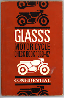
GLASS’S MOTOR CYCLE CHECK BOOK…Glass’s Guide
This little gem of a booklet is little known amongst even literature collectors in our classic/vintage motorcycle movement, un-illustrated, it contains a mine of information on dating, with engine, frame numbers and changes to specifications during a model production.
It was produced for the motorcycle trade to assist them to identify models being traded in on another purchase and to work out a price. Glasses also produced a monthly “Glasses Guide to used motorcycle prices” to compliment the check book. Who are Glass’s ?
Glass's is part of the privately-owned EurotaxGlass group of companies that has operations in more than 30 European countries.
Automotive data is at the centre of the entire operation and the group provides leading-edge solutions to more than 25,000 customers across Europe in all sectors of the automotive market.
In the UK, Glass's employs almost 200 staff and is based in Weybridge, Surrey, UK.
William Glass was born in Scotland in 1881 and was an engineer by trade. As well as publishing the first Guide to Used Vehicle Values, Glass had an innovative and enquiring mind and made a number of inventions including the portable hydraulic jack, the electric switch-off kettle, the self-filling fountain pen and the through-the-propeller machine gun firing mechanism.
The founder of Glass’s Guide also manufactured cars under the Firefly marque for a short period of time in Croydon. Glass’s other innovations included the first motor auction and the first uniformed attendants at petrol filling stations.
Glass's was founded in 1933 by William Glass and the first Guide to Car Values was published in July of that year. Since that time the company has expanded into Commercial Vehicle, Motorcycle and Caravan values, supplying data in printed, electronic and web formats.Of interest to us is the small Motor Cycle Check Book, first published in 1957 and covering from just before 1950 to 1957, The next issue, which I have, as well as a range of several more check books up to about 1979, ran from 1950-1959 and is illustrated in this blog.
As you rarely see them for sale, I can’t hazard a guess at the price….
Left click on photos to enlarge.
Sunday, July 13, 2008
The 348 c.c. KTT Mk.8 VELOCETTE engine analysis....
The 348 c.c. Overhead camshaft KTT VELOCETTE ... Whys and wherefores of a Famous Engine Designed Specifically for Road Racing By "Ubique", a nome-de-plume by a journalist for "The Motor Cycle" and published in "Motor Cycle Engines".....
Everyone knows that, for years, the KTT Velocette was unique in being the nearest possible thing to a genuine T.T. model which was available to the public. It was, in fact, designed and intended for road racing, and this must be remembered when considering the following notes.
Looking at all the parts neatly laid out on the sheets of brown paper, I was at a loss to know where to begin. Finally, after discussing the point with Messrs. Percy Goodman and Harold Willis-now, unhappily the late Harold Willis- I decided to start at the top and work down, yet in actual practice my first question dealt with the cylinder barrel. "What are the materials, and how are they mated?"
Rather to my surprise I learned that the silicon-aluminium-alloy jacket with its very deep radiating ribs, was "cast on," the nickel cast-iron barrel, with its corrugated outer wall, being heated and placed in the mould before the alloy was poured.
Mr. Willis did not think there was much to choose between this practice and that of pressing-in a liner or shrinking-on a jacket, but actually Velocettes, he said, had had slightly better results with the practice outlined; it prevents the possibility of the liner "creeping."
The head, I gathered, was of heat-treated "Y"-alloy, a metal chosen for its light-weight, strength and high thermal conductivity. The head ribs of the KTT are roughly 9in square in plan view, and the camshaft casing and the boxes for the enclosure of both valves and their double hairpin valve springs are cast with the head, so you can judge the importance of a lightweight material.
Of course, I asked why these huge cooling fins were employed, suggesting that it must be almost impossible for a considerable draught of air to reach the rib roots.
In this matter Mr. Willis told me I was correct, but that careful tests showed that it was of greater importance to get a big cooling surface right out into the draught then to rely on such air as might possibly pass the front wheel, mudguard, fork, frame, etc., reaching the roots of the fins. That explains the importance of high conductivity, does it not?
Again, he pointed out that the joint between the head and barrel, at the top of the spigot, consisted of a laminated copper washer. Each of the four laminations is about 0.009 in thick, and this arrangement makes a very satisfactory job with direct metal-to-metal contacts throughout.
Internally, the head is approximately hemispherical, the long-reach 14mm plug being placed on high up and screwed directly into the head.
My next question was, "Why do you employ different materials for exhaust and inlet valve seating?"
"A hard aluminium-bronze alloy is used for the exhaust seat, because of the high conductivity of this metal helps to keep the exhaust valve cool and, incidentally, its high co-efficient of expansion helps to maintain good contact with the head casting at high temperatures."For the inlet valve, the seat of which is apt to be damaged by grit, a nickel cast-iron is employed on account of tis hardness."
Pressed-in Seatings
"How are the seatings help in position?" I then asked.
"The head is heated in an electrical furnace to a temperature of 200 degrees C., and the seatings previously mounted on special jigs, are pushed home very quickly. Speed is essential in this process, for as soon as the seatings come in contact with the hot head, they also expand and lock in position."
The pale gold of aluminium-bronze valve guides next caught my eye. The high heat conductivity and high coefficient of expansion, plus the fact that this material is an excellent bearing metal, make it very suitable for the purpose. Add to this, ample lubrication from the cam-box and the very high finish of the valve stems and guides, and I was not surprised to hear that wear at this point is negligible over long periods.
Incidentally, the valve stems work with quite close clearance limits, the actual figures being 0.0015in for the inlet and 0.003in for the exhaust.
"Why is the inlet valve of larger diameter that the exhaust?" Both my mentors answered this question. Perhaps I may summarize their remarks by saying that it is far more difficult to fill a cylinder by atmospheric pressure than to empty it when the piston pushes behind and there is help at certain vital speeds from a specially designed exhaust pipe.
"The valves themselves? Well, the inlet is made of a cobalt-chrome steel having high tensile strength and hard wearing surfaces. It has a throat diameter of 1 9/16in, an the stem is reduced to the smallest possible diameter consistent with safety, so as to reduce port obstruction. K.E.965 steel was chosen for the exhaust valve because it retains great strength at the very high temperatures at which it is called upon to work.
Valve Timing
The port diameter of the exhaust valve is 1 7/16in, and the stem is approximately 1/16in larger than that of the inlet, and the lift of both valves is 3/8in. Both have moderately recessed heads, but whereas the end of the inlet stem is hardened, the material of the exhaust is unsuited for this purpose, so a hardened end-cap is used.
I asked if the valve timing were a secret, but it was given me without the slightest hesitation. Checked with a tappet clearance of 0.020in in each case, the timing is as follows : inlet opens 55º BTDC, and closes 65º ABDC.; exhaust opens 75º BBDC. & closes 45º ATDC.
One hundred degrees overlap. Think of it! That ought to get the inlet gas column moving and ensure that the valve are well open when they will do most good!
The correct running tappet clearances are: inlet 0.0015in, exhaust 0.025in.
Even the details of the valve spring cup and collect are of unusual interest. It was pointed out that the groove in the top of the valve stem is extremely shallow in order to reduce the strength of the stem as little as possible. To make up for this the split collett is so designed as to grip the stem, and under the wedging action of the spring cup this grip is almost sufficient without the groove.
Free to Rotate
The item which corresponds to the usual spring cup (and is described as such above) does not, in fact, form a direct thrust face for the hairpin springs, the looped ends of which are hooked on to a separate steel spring abutment, loosely mounted round the "spring cup." Thus, at the expense of a little extra reciprocating weight, the valve is free to rotate, a most desirable feature.
At their lower ends the valve springs are tucked into longitudinal holes drilled in a steel plate which surrounds the upper part of the valve guides. And these plates have at each end, a tapped hole to carry the fulcrum of a spring removing tool.
"What spring pressures are necessary for this engine?" I asked.
"Measures with the valve closed, a pressure of 110lb, plus another 25lb for the return spring on the rocker, the latter an important point which we will discuss when we get there."
"Does the total enclosure of the valve gear cause any kind of trouble in the way of overheating?"
"No, the valve boxes have a large external area exposed to the draught and the interior is cooled by a liberal circulation of oil."
"Some years ago you used a two-cam-shaft racing engine," I said. "Why, in the this engine, have you reverted to the single-camshaft type?"
"I was about to mention that very point," said Mr Percy, " as ti is a matter of some historical interest. The twin-camshaft job, in spite of its theoretical advantages, presented certain practical difficulties. (Since overcome as recent Velocette racing engines have demonstrated.-Ed) It was difficult to provide reasonably accessible tappet adjustment, and to enclose the mechanism-a point which, as you know, we consider to be important. Further, for the first time we had trouble with the vertical shaft drive, which could be traced indirectly to the upper works of the valve gear."
Mr. Willis continued: "After much experiment we found that the best of all round results could be obtained from a single-camshaft engine if the rockers could be held in constant contact with the cam. This led to the powerful hairpin rocker return spring which you are examining. At first this caused scoring and rapid wear of the rocker heels and cams, and we found it necessary not only to provide a jet of oil directly on to the point of contact between cam and rocker, but also to face the heel of the rocker with Stellite. These precautions have been completely successful.
Floating Bushes
On inquiry, I found that these rockers are made from stampings of air-hardening, nickel-chrome steel of 100-ton tensile test. Between each rocker and its massive eccentrically mounted pivot-pin is a bronze floating bush.
"Why are the cams made separate from their shaft?"
"Well, the cams, which are designed to give constant valve acceleration and deceleration are of a straight carbon-steel, deeply cased, and have 1 per cent carbon in the case. The shaft is of 3 per cent nickel steel, case-hardened so as to form a track for the driving-side roller bearing. The cams are pressed and keyed on to the shaft. The rollers on the drive side are caged and a ball-bearing on the other end of the shaft takes the end thrust from the bevel gears."
"What about the vertical-shaft drive?"
"Most of it is standard, including the upper pair of bevels. The crown bevel is bolted to its back place by four bolts, and the bolt holes are elongated to provide a half tooth adjustment for timing. The lower bevels have been strengthened to withstand the extra strains imposed by high speed and heavy valve springs."
"Why the lower bevels and not the upper ones?"
"Because the shape of the small-diameter bevels of approximately bevels of not so favourable to tooth strength."
"I note you retain the hunting tooth."
"Yes, the odd teeth in the vertical-shaft drive distribute the loading as evenly as possible. The vertical-shaft bevels are mounted in bronze journal bushes, the thrust being taken on the end faces. Steel rings are lightly pressed on to the shafts to locate the bevels length-wise in their bearings. There is an Oldham coupling of oil-hardened nickel-chrome steel between each bevel shaft and the solid steel coupling shaft. This coupling shaft is mounted in plain bearings in tis enclosing tube, and the tube is held at each end by asbestos-packed gland-nuts, and although it appears to be quite rigid, there is just a trace of intentional flexibility in the mounting."
The unusually narrow aluminium-alloy crankcase is noticeable without need of questions, and the single-row caged roller bearings on each side are supported directly under the massive walls in which the main
strength of the crankcase lies. The only additional stiffening is provided by shallow webs on the outside of the drive side. As in other Velocette models , the primary drive lies inside the final drive, and therefore the engine spoket is close up to the main bearing. Thus, there is very little overhang and no need for a multiplicity of crank bearings.
Immense Rigidity
A glance at the compact and immensely rigid crank unit with its single-row big-end and comparatively narrow (13/16in) flywheels, also at the smooth, web-less interior of the crankcase, shows how that effect of slimness is attained, but here more questions were necessary.
"What are the flywheels made of?"
"Heat-treated carbon steel."
"Why heat-treated?"
"To prevent stretch in the shaft holes."
"How are the crank axles fixed in the flywheels?"
"Just pressed in, and located the pin.”
"The pin is really a screw lying parallel with the shaft, partly in the shaft and partly in the flywheel bass. These shafts, of 3 per cent nickel steel, are very slightly tapered so that the inner races of the main bearings are securely locked when pushed home. The outer races are shrunk in to the crankcase, so that they also are firmly held."
Then I asked about the massive crank-pin, which adds so materially to the rigidity of the crank unit. It is made of nickel-chrome steel, case hardened to form the inner race of the big-end bearing. The main diameter is 1 3/8 in, and the ends are very slightly tapered and pulled into the flywheels against wide shoulders. The nuts which fix it are of heat-treated nickel steel.
Rollers of 9/16in x 3/16in are employed in the big-end bearing. These rollers are located in a Duralumin cage, the bars of the cage being relieved on their inner surface so that the only end rings of the cage bear on the crankpin.
The reason for this is that the Duralumin cage is apt to wear the hardened crankpin, and the relief of the bars prevents damage to the roller track. This, of course, is a fact, though it may seem hard to believe that more wear is caused by the light-alloy cage than the heavily loaded rollers. The outer race of the bearing is pressed into the connecting rod big-end and a bronze bush into the small-end.
The massive forged connecting rod is made form an oil hardening nickel-chrome steel, heat-treated to about 80 tons tensile. "Of course," said Mr. Willis, "we could use a steel with higher tensile strength, but tensile strength is not the only necessity, for the great toughness is also required. The rod is machined all over and polished on the outside. This is not only useful for removing surface scale and weight, but also tends to reveal surface cracks or flaws."
Of case-hardened nickel-chrome steel, the gudgeon pin is no less than 13/16in diameter; it is hollow and is taper bored at the ends to reduce weight. It floats in the little-end of the connecting rod, and is retained in the piston bosses by spring-wire circlips. As was pointed out, the outer extremities of the gudgeon pin are so chamfered that any tendency for the pin to move endways tens to also to jamb the circlips in their grooves, rather than to displace them.In order to provide the standard compression ratio of approximately 10.9 to 1, the piston head must be steeply domed. It is! So much so, indeed, that circular pockets are formed in the sides of the dome to clear the valve heads.
The skirt is of slipper form, and the whole is made of heat treated "Y"-alloy, sand-cast,
"Why sand-cast?" I asked.
"Because it has given us better results that way," was the reply.
There are small, vertical ribs from the gudgeon-pin bosses upwards, and there is a circular rib at the level of the boss centres for maintaining the shape of the slippers. Two narrow pressure rings of Wellworthy "Themocrom" (heat-formed, not hammered) and a slotted scraper ring are fitted.
"Each engine, individually, is adjusted by shims under the cylinder base so that the cylinder head capacity is 35c.c.," said Mr. Willis.
This 348c.c. engine develops 27 b.h.p. at 6,500 r.p.m. It may be run at 7,000 r.p.m. in the normal course of events, and may be run with safety up to 7,500 r.p.m. for short periods, and will run up to 8,000, though this is considered to be beyond the limits of reasonable safety.
The port diameter of the exhaust valve is 1 7/16in, and the stem is approximately 1/16in larger than that of the inlet, and the lift of both valves is 3/8in. Both have moderately recessed heads, but whereas the end of the inlet stem is hardened, the material of the exhaust is unsuited for this purpose, so a hardened end-cap is used.
I asked if the valve timing were a secret, but it was given me without the slightest hesitation. Checked with a tappet clearance of 0.020in in each case, the timing is as follows : inlet opens 55º BTDC, and closes 65º ABDC.; exhaust opens 75º BBDC. & closes 45º ATDC.
One hundred degrees overlap. Think of it! That ought to get the inlet gas column moving and ensure that the valve are well open when they will do most good!
The correct running tappet clearances are: inlet 0.0015in, exhaust 0.025in.
Even the details of the valve spring cup and collect are of unusual interest. It was pointed out that the groove in the top of the valve stem is extremely shallow in order to reduce the strength of the stem as little as possible. To make up for this the split collett is so designed as to grip the stem, and under the wedging action of the spring cup this grip is almost sufficient without the groove.
Free to Rotate
The item which corresponds to the usual spring cup (and is described as such above) does not, in fact, form a direct thrust face for the hairpin springs, the looped ends of which are hooked on to a separate steel spring abutment, loosely mounted round the "spring cup." Thus, at the expense of a little extra reciprocating weight, the valve is free to rotate, a most desirable feature.
At their lower ends the valve springs are tucked into longitudinal holes drilled in a steel plate which surrounds the upper part of the valve guides. And these plates have at each end, a tapped hole to carry the fulcrum of a spring removing tool.
"What spring pressures are necessary for this engine?" I asked.
"Measures with the valve closed, a pressure of 110lb, plus another 25lb for the return spring on the rocker, the latter an important point which we will discuss when we get there."
"Does the total enclosure of the valve gear cause any kind of trouble in the way of overheating?"
"No, the valve boxes have a large external area exposed to the draught and the interior is cooled by a liberal circulation of oil."
"Some years ago you used a two-cam-shaft racing engine," I said. "Why, in the this engine, have you reverted to the single-camshaft type?"
"I was about to mention that very point," said Mr Percy, " as ti is a matter of some historical interest. The twin-camshaft job, in spite of its theoretical advantages, presented certain practical difficulties. (Since overcome as recent Velocette racing engines have demonstrated.-Ed) It was difficult to provide reasonably accessible tappet adjustment, and to enclose the mechanism-a point which, as you know, we consider to be important. Further, for the first time we had trouble with the vertical shaft drive, which could be traced indirectly to the upper works of the valve gear."
Mr. Willis continued: "After much experiment we found that the best of all round results could be obtained from a single-camshaft engine if the rockers could be held in constant contact with the cam. This led to the powerful hairpin rocker return spring which you are examining. At first this caused scoring and rapid wear of the rocker heels and cams, and we found it necessary not only to provide a jet of oil directly on to the point of contact between cam and rocker, but also to face the heel of the rocker with Stellite. These precautions have been completely successful.
Floating Bushes
On inquiry, I found that these rockers are made from stampings of air-hardening, nickel-chrome steel of 100-ton tensile test. Between each rocker and its massive eccentrically mounted pivot-pin is a bronze floating bush.
"Why are the cams made separate from their shaft?"
"Well, the cams, which are designed to give constant valve acceleration and deceleration are of a straight carbon-steel, deeply cased, and have 1 per cent carbon in the case. The shaft is of 3 per cent nickel steel, case-hardened so as to form a track for the driving-side roller bearing. The cams are pressed and keyed on to the shaft. The rollers on the drive side are caged and a ball-bearing on the other end of the shaft takes the end thrust from the bevel gears."
"What about the vertical-shaft drive?"
"Most of it is standard, including the upper pair of bevels. The crown bevel is bolted to its back place by four bolts, and the bolt holes are elongated to provide a half tooth adjustment for timing. The lower bevels have been strengthened to withstand the extra strains imposed by high speed and heavy valve springs."
"Why the lower bevels and not the upper ones?"
"Because the shape of the small-diameter bevels of approximately bevels of not so favourable to tooth strength."
"I note you retain the hunting tooth."
"Yes, the odd teeth in the vertical-shaft drive distribute the loading as evenly as possible. The vertical-shaft bevels are mounted in bronze journal bushes, the thrust being taken on the end faces. Steel rings are lightly pressed on to the shafts to locate the bevels length-wise in their bearings. There is an Oldham coupling of oil-hardened nickel-chrome steel between each bevel shaft and the solid steel coupling shaft. This coupling shaft is mounted in plain bearings in tis enclosing tube, and the tube is held at each end by asbestos-packed gland-nuts, and although it appears to be quite rigid, there is just a trace of intentional flexibility in the mounting."
The unusually narrow aluminium-alloy crankcase is noticeable without need of questions, and the single-row caged roller bearings on each side are supported directly under the massive walls in which the main
strength of the crankcase lies. The only additional stiffening is provided by shallow webs on the outside of the drive side. As in other Velocette models , the primary drive lies inside the final drive, and therefore the engine spoket is close up to the main bearing. Thus, there is very little overhang and no need for a multiplicity of crank bearings.
Immense Rigidity
A glance at the compact and immensely rigid crank unit with its single-row big-end and comparatively narrow (13/16in) flywheels, also at the smooth, web-less interior of the crankcase, shows how that effect of slimness is attained, but here more questions were necessary.
"What are the flywheels made of?"
"Heat-treated carbon steel."
"Why heat-treated?"
"To prevent stretch in the shaft holes."
"How are the crank axles fixed in the flywheels?"
"Just pressed in, and located the pin.”
"The pin is really a screw lying parallel with the shaft, partly in the shaft and partly in the flywheel bass. These shafts, of 3 per cent nickel steel, are very slightly tapered so that the inner races of the main bearings are securely locked when pushed home. The outer races are shrunk in to the crankcase, so that they also are firmly held."
Then I asked about the massive crank-pin, which adds so materially to the rigidity of the crank unit. It is made of nickel-chrome steel, case hardened to form the inner race of the big-end bearing. The main diameter is 1 3/8 in, and the ends are very slightly tapered and pulled into the flywheels against wide shoulders. The nuts which fix it are of heat-treated nickel steel.
Rollers of 9/16in x 3/16in are employed in the big-end bearing. These rollers are located in a Duralumin cage, the bars of the cage being relieved on their inner surface so that the only end rings of the cage bear on the crankpin.
The reason for this is that the Duralumin cage is apt to wear the hardened crankpin, and the relief of the bars prevents damage to the roller track. This, of course, is a fact, though it may seem hard to believe that more wear is caused by the light-alloy cage than the heavily loaded rollers. The outer race of the bearing is pressed into the connecting rod big-end and a bronze bush into the small-end.
The massive forged connecting rod is made form an oil hardening nickel-chrome steel, heat-treated to about 80 tons tensile. "Of course," said Mr. Willis, "we could use a steel with higher tensile strength, but tensile strength is not the only necessity, for the great toughness is also required. The rod is machined all over and polished on the outside. This is not only useful for removing surface scale and weight, but also tends to reveal surface cracks or flaws."
Of case-hardened nickel-chrome steel, the gudgeon pin is no less than 13/16in diameter; it is hollow and is taper bored at the ends to reduce weight. It floats in the little-end of the connecting rod, and is retained in the piston bosses by spring-wire circlips. As was pointed out, the outer extremities of the gudgeon pin are so chamfered that any tendency for the pin to move endways tens to also to jamb the circlips in their grooves, rather than to displace them.In order to provide the standard compression ratio of approximately 10.9 to 1, the piston head must be steeply domed. It is! So much so, indeed, that circular pockets are formed in the sides of the dome to clear the valve heads.
The skirt is of slipper form, and the whole is made of heat treated "Y"-alloy, sand-cast,
"Why sand-cast?" I asked.
"Because it has given us better results that way," was the reply.
There are small, vertical ribs from the gudgeon-pin bosses upwards, and there is a circular rib at the level of the boss centres for maintaining the shape of the slippers. Two narrow pressure rings of Wellworthy "Themocrom" (heat-formed, not hammered) and a slotted scraper ring are fitted.
"Each engine, individually, is adjusted by shims under the cylinder base so that the cylinder head capacity is 35c.c.," said Mr. Willis.
This 348c.c. engine develops 27 b.h.p. at 6,500 r.p.m. It may be run at 7,000 r.p.m. in the normal course of events, and may be run with safety up to 7,500 r.p.m. for short periods, and will run up to 8,000, though this is considered to be beyond the limits of reasonable safety.
Copied from "Motor Cycle Engines", published by The Motor Cycle, approx.1951 with acknowledgement to Mortons Motorcycle Media, holders of the copyright.
I also published this in the Australian Velocette Owners Club magazine FTDU329 spring 2004.
Left click on photos to enlarge.
Subscribe to:
Posts (Atom)