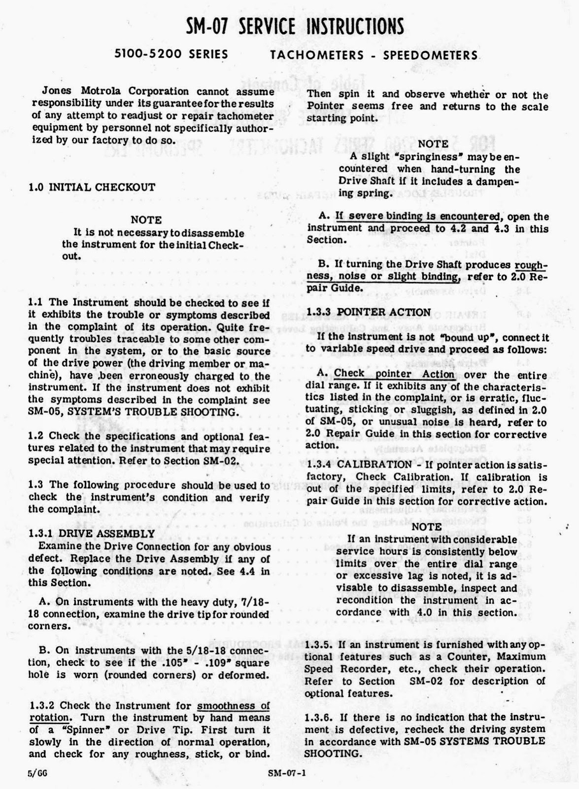
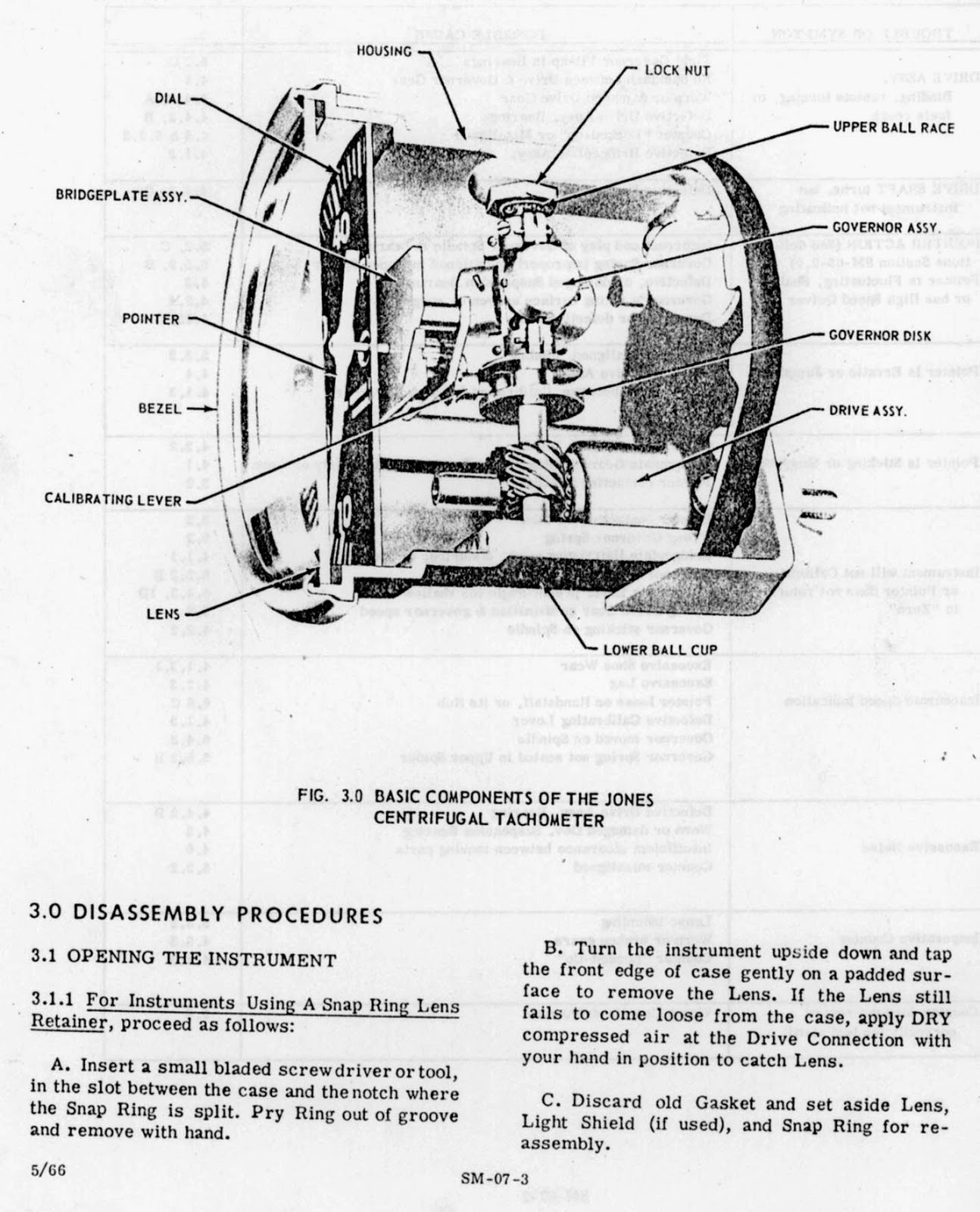
As mentioned in the previous post on Jones tachometers this second post contains the calibration instruction for the Jones centrifugal mechanical tachometerand completes the information I have on them. They differ from the Smiths centrifugal speedometer and tachometer in the method of calibration and is more precise as a result. The Smiths instrument had a dial scale which was not linear whereas the Jones is linear. This meant the Smiths instrument had a series of different dial scales available as part of the calibration method, some seven different dial for their 60mph speedo for example...I will do a post on the Smiths centrifugal/governor speedometer in a future post... Service Instructions for the Jones Motrola 5100-5200 series speedometer and tachometer..
As some of you will have realised, perusing my weblog, The Velobanjogent was in the automotive, more specifically the motorcycle instrument business for over 30 years and during this time worked on just about all the various speedometers and tachometers that were used on vehicles. I've done numerous posts on them from my personal memory and large archive of literature and photographs of automotive instruments.... I can't take them with me "when I leave this mortal coil" so I get great pleasure in sharing as much as I can.... What have I this time...? The Jones Instrument Corporation in Stamford, Connecticut,USA were making speedometers from the start of the 20th century....
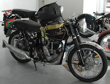
Pretty poor condition 1910 Jones speedometer....
Advert from the English "The Motorcycle" magazine, November 1908...
In 1986 I made a visit to Jones Corpn. in Stamford, CT after struggling with the repair and calibration of the racing tachometers I occasionally had pass through my instrument shop....so I was unsure what to expect when I went there, flying across the Pacific and the USA to visit them...they were more than helpful, no speedometer parts left and not prepared to sell parts for the maximum hand racing tachometers they still made, but quite happy to provide me with catalogues and the service/calibration sheets for these tachos.... Lets look for a start at a some catalogues from around the late 1960s and 1980s....
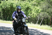
Because of the number of pages in the repair/calibration manual I'll feature it in my next blog which as I'm off to Europe for 18days from the 21st March on another Velocette historical/archival foray will be mid April..... The Velobanjogent is meeting up with some Velo friends in Germany and Holland and Dai Gibbison in the UK.... Pictured is myself with the guys with Gert Boll's rare mk.6 KTT Velocette in August 2013...
Smiths, the UK based instrument firm, had made special tachometers for competition since the early 1930s.
Initially based on the chronometric principle and I’ve touched on these in earlier postings in my blog, they introduced magnetic mechanically driven tachometers based on the eddy current principle in production cars and aircraft, from the later 1930s culminating in the ATRC version in the mid 1950s.
ATRC..??
The initials stand for Auto Tempo Racing ( and) Competition. The Auto Tempo part is from a company Smiths took over in the late 1920s and who supplied instruments utilising the eddy current principle and with a method of construction that Smiths continued with in their version.
Bentley and Rolls Royce cars used AT speedometers and tachometers from the 1920s up until the early 1970s when Smiths ceased production.
There was a London based company, Auto Tempo, that did instrument repairs, run by Joe Shaw, but I don’t believe they were connected in any way. I dealt with them in the late 1970s-80s.
The competition ATRC tachometers are 80mm (3”) in diameter…interesting this, as many of Smith’s instruments are in metric dimensions, having utilised this since the late 1920s when they acquired the French based Jaeger ED company, set up shortly before in the UK, and renamed it British Jaeger, who of course made their instruments to metric dimensions.
The bezel rim, same in construction as used on the Smiths Chronometric tachometer has an 80.00mm diameter x 0.90mm thread to screw on.. Yes it is not imperial and not 26tpi….
The bezel used on the ATRC has a Satin Chrome finish, to minimize glare from the sun blinding the rider or driver.
The body is an aluminium casting, machined internally, operating on the eddy current principle, each instrument incorporates a rotating magnet of special alloy and a movement carried on jewels. Individually manufactured and calibrated, the construction is such that variations due to temperature changes are within the limits of accuracy for this instrument. This is 1% of full scale in the temperature range 10-30°C. The mainshaft was carried in two ball race bearings, unusual for a tachometer or speedometer which are usually constructed using a bush assembly. This indicates the "specialness" of these tachometers...they really are "The Rolls Royce of instruments".
They were available in both clockwise and anti-clockwise dial scale ranges for 9000rpm, 10000rpm and 12000rpm, and clockwise only for 15000rpm, 18000rpm, 20000rpm and 22000rpm.
The last three were for Honda Motor Corporation who used them on their works racers in the 1960s.
BMW used a 10000rpm c/wise 2-1 version on their Rennsport engines used in the 1950s and 1960s.
The 12000rpm scales were used by NSU on their works racers and Sportsmax production racers ( 12000rpm anti c/wise dial scale), Gilera 4 cylinder factory racers ( 12000rpm anti c/wise dial scale), some MV Augusta racers, although they often used the 80mm dia. “white faced” competition tachos as did Moto Guzzi, although the V8 Moto Guzzi was supplied with an ATRC from Smiths.
CZ, Jawa etc also used Smiths instruments.
They must be used with an anti vibration mounting, code MS1001/00, manufactured for Smiths with the tachometer sitting on a central plate connected to an outer ring ( for attachment to the motorcycle fairing or cockpit, or car dash area) via an “O” ring in four places.
This provides a large amount of insulation from engine vibration and road shock.
The most commonly known use of the ATRC competition tachometer, was in the 9000rpm c/wise dial scale form ( code ATRC2652) used since 1956 to their closure in 1962 on AMC raceware…the 350 and 500 Manx Norton, the 350 7R AJS and the 500 G50 Matchless.
These were supplied with the cable connecting directly to the bottom of the tachometer via a 12mm x 1mm thread.
After 1962 as the dolphin fairing became utilised, Smiths made the ATRC tachometer with a built in 90° 1-1 non reversing angle drive fitted.
This allowed a better cable run to the tachometer drive on the AMC racers and was often utilised by others such as Honda Motor etc.
As well an interesting snippet is some time back, when John Surtees owned the ex works 500cc supercharged rennsport BMW that Georg Meier won the 1939 Senior IOM TT on, he was particular over his engine preparation and as the bike didn't have a tachometer fitted as standard in the period, he asked me to make him a 9000rpm ATRC 2-1 tachometer with a white face and the scale was as the normal ATRC, but the dial marking were from a German tachometer of the period, R.Muehle u.Sohn, Glashuettle/Sa.
A small Smiths screw-on 90° angle drive can be fitted to the straight cable entry tachometers, they are available as BG2410 a 1-1 non reversing type, or if you need to reverse the direction of the cable as it enters the tachometer because the scale goes “the wrong way” for your application, you could use the same small drive, coded as BG2412 a 1-1 reversing drive. These are pictured.
Pictured are some dial scale types from my dial catalogue….
How does this "eddy current principle" ATRC tachometer work?
Inside the tachometer is a magnet assembly driven by the drive cable.
As the magnet spins, it sets up a rotating magnetic field, causing electric current to flow in the aluminium detecting disc that closely surrounds it.This is called the speedcup which is the detecting disc. The electrical current that flows in the cup are small rotating eddies, known as eddy currents.The eddy currents themselves have a magnetic field around them and these are repelled by the spinning magnetic field from the magnet.
The cup and its attached needle turn in the same direction that the magnetic field is turning -- but the hairspring attached to the shaft in the centre of the speedcup resists the movement of the cup.The needle on the speedcup stops where the opposing force of the hairspring balances the force created by the revolving magnet.
What if the engine increases or decreases its speed? If the engine speed increases, the magnet within the speedcup will rotate faster, which creates a stronger magnetic field, larger eddy currents and a greater deflection of the tachometer needle. If the engine slows down, the magnet inside the cup rotates more slowly, which reduces the strength of the magnetic field, resulting in smaller eddy currents and less deflection of the needle.
When the engine finally stops, the hairspring , because of a zero error setting, holds the needle at a rest position ( which may not be “0”, as in the case of the ATRC whose dials start at 1000rpm, 5000rpm etc.)
I still manufacture these original type ATRC tachometers to the same specification as those from Smiths, with my manufacturing the case, bezel rim, dial, pointer, anti-vibration
mount and utilizing an industrial version of
this Smiths AT movement, identical in
operation to that originally used by Smiths.
I can repair the original versions utilising this parts source.
Also pictured are parts of the “internals” of the tachometer, with a movement with the speedcup and pointer assembly in a jig for setting the zero error to the dial.
As mentioned Honda Motor used these tachometers on their factory machines....pictured is a 16000rpm version on the former Mike Hailwood works 500/4 Honda, now owned by Virgil Ewings from California.
Included is part of a page from the notes of the late Jack Owens, last manager of the Smiths Competition Dept., Oxgate Lane, London, UK.
Acknowledgement of items used in this Blog from my archive...
I often feature items from older Motorcycle magazines, including photographs and other drawings, cartoons etc in my Blog. Where possible I acknowledge their source. These items are often from "MotorCycle" and "MotorCycling", and the current copyright holders are Mortons Motor Cycle Media. I thank them for their use.
Where other sources are used such as Fox Photos, Keystone Press and other now defunct press agencies from the UK and elsewhere I attempt to acknowledge their source.
You are free to use any item from my Blog, but PLEASE give credit to the source.
Search This Blog
A photo I like....!
BMS in 1961 aboard a road test Velocette Venom Clubman Veeline
DQs Thruxton in the 1971 Castrol 6 hour Race, Amaroo Park,Sydney.
My co-rider, Dennis Fry, looking the consumate racer,probably the last to use a pudding basin helmet in competition...
DQs Thruxton in the 1971 Castrol 6 hour Race, Amaroo Park,Sydney.
DQ aboard his VMT during the first 2 hour stint, pictured in Brabham loop
VMT458 at the 2012 Australian Velocette Owners Club National Rally at Bundanoon, NSW.
DQ reunited with VMT458 after 32 years
VMT458 at the 2012 National Velocette Owners Club Rally at Bundanoon, NSW
Dennis Fry re-united with VMT458, DQs co-rider in the 1971 Castrol 6 hour race
Ready for another US Velo Ride
My 1962/1948 KSS/Scrambler Velo road bike, built in Canada in 1976 and imported into Sydney, Australia, May 2012 for use in local Australian Velo events......
DQ on his Velo Special
Riding in the Napa, Cal. area May 2010
DQ on his second KSS engined RS framed Velocette
Velo Thruxton at speed
North American Velo OC logo used for one of the Club's annual rally and rides
I've motorcycled since the early 1960s...both in Australia, the USA,NZ and UK to where my long suffering wife and I rode a 1972 BMW R50/5 motorcycle via the overland route through Asia in 1974. Careers in Animal Physiology and Automotive Instruments and now finally semi retired into music...as a banjoist in Trad./Dixieland Jazz bands.
Life for me is very interesting......