 of the Similar 192c.c. Mount-and CHARLES UDALL, Development Engineer, Provides the Answers..
 “The component parts of the LE engine are all straightforward. It is the fact that they have been ‘gathered together’-shall we say?-in the way that they have that makes the machine appear unorthodox. It is true to say that in the complete machine not a single departure has been made from what is regarded today as normal engineering principles; obviously to depart from these would have spelt trouble-in large capital letters!”
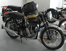
The photo at the top shows Anne Frampton, daughter of Bertie Goodman last managing director of Veloce Ltd ( himself son of Percy Goodman, the brilliant designer of so many early Velocette engines and inovations) astride Peter Wolfenden's Mk.2 LE at the NSW section of the Australian Velocette Owners Club Show Day at "Fagan Park", on the Northern outskirts of Sydney, 31st August 2008.
Anne is the Club Patron and lives in Sydney.
Thus spoke Mr. Charles Udall, Velocette development Engineer, when I called at the works to discuss the whys and wherefores behind the ingenious design of the 150 c.c. LE Velocette- the most revolutionary lightweight of the day.
“In discussing the LE unit,” he continued, “ I’m afraid that it may be necessary to depart from the strict confines of your ‘Modern Engines’ series. You see, the LE is a conceived-as-a-whole design. The engine, gear box, propeller-shaft, and bevel box all form an integral unit; an entity; a single unit designed to do a specific job. And it is impossible to discuss on ‘section’ of the unit without bringing in a sister section.”
 From this stimulating gambit we passed on to a discussion that carried us non-stop through an absorbingly interesting afternoon.
My first question was a multiple one: “Why did you decide on a flat-twin and why, indeed, on a twin at all? Did you ever consider employing a single- a two stroke for instance?”
“Well, first of all,” replied Mr. Udall, “one of the primary aims was elimination, in so far as was possible, of all forms of vibration. There are only three types of engine which could be considered, and of those the flat-twin is really suitable for use in a small-capacity motor cycle. The four-cylinder engine also, of course, eliminates vibration, but obviously the LE is not the sort of machine which could be fitted with a “four.” Whit single, the whole machine would have had to have been made heavier to withstand the inherent vibration, and the steel frame as it exists in the LE today would have proved quite useless. So the question of using a single was never considered, nor was the question of making the engine a two-stroke.
 “Again,” Mr. Udall continued, “we come to my other point about one thing leading to another. Since one of the chief aims as I have said, was the elimination of vibration, a flat-twin was decided upon. Since the unit had to be as simple as possible, and lage mileages with a minimum of attention were an important proviso, side-by-side valves were preferred. An objection to overhead-valves was that even a small-capacity engine, the width would considerably be increased, making the engine much more vulnerable. The cylinder heads, in fact, would probably have protected beyond the legshields.
“Linked with the question of ease of maintenance was the decision to use shaft-drive. True, shaft-drive is more expensive than chain. But having a shaft greatly simplifies maintenance for the non-mechanically minded rider, who may be using the machine every day. And the chief aim, after all, was to provide for low maintenance cost as opposed to the lowest production cost.
“The decision to employ shaft-drive arrived at mounting the engine transversely in the frame was a sine qua non. Cooling? Water-cooling was the obvious answer for two reasons; the first was that it is possible to obtain a much higher degree of mechanical quietness when the cylinders are shrouded by water jackets. Taking the conception of the machine as a whole again, legshields must be regarded in the light of essentials, and if air-cooling had been employed, gaps in the shields for the air stream would have been necessary. And that, of course, would have affected weather protection. Another point was that the engine temperature of a small side-valve unit is more easily controlled by means of water-cooling.”
Going into his last point in greater detail, Mr. Udall pointed out that had air-cooling been employed, it would have been next to impossible to incorporate air passages round the exhaust ports.
“The manufacture of engine, clutch, gear box, and final drive as a single unit promised simplification in assembly and manufacturing problems which could not be ignored. Hence the unit construction.”
 In one fell swoop, as it were, Mr. Udall had answered about a dozen of the points listed on the rough questionnaire I had prepared. I decided I had better scrap it right away, and deal with each field of inquiry as it cropped up!
Leaving generalities, Mr. Udall went on to point out that the crankshaft is of the two-throw type with the cranks at 180 deg. Since the aim was to keep the offset on the cylinders as low as possible in order to reduce the out-of-balance couple to a minimum, it was desirable to keep down the width of the big-ends. Thus roller-bearings were used. Had plain bearings been adopted, the cylinders would have required to be considerably more offset than they are now, since, in order to achieve the desired load-carrying capacity, considerably wider bearings would have been needed.
The rollers in the big-end bearings are uncaged. There are 28 rollers per bearing. The size of the big-end track on the crankpin is 1in dia. When talking of the big-end track, Udall was referring not to the crankpin itself, but to the hardened sleeve which is pressed on the crankpin.
The obvious question to all of this was: “But why use these sleeves at all- why not a plain, hardened pin of larger sections and grind the bearing surface?”
“Ah!” said Charles, “ that requires some explanation. As you can see. The crankpins and crank discs are a one-piece forging. The metal used is a 3 ½ per cent nickel steel, in fact, B.E.S.69. This is a steel with a high tensile strength and one that is quite ductile. In order to minimize the risk of fracture, and avoid cracks in the angles formed by the pin and disc, these corners have to be radiused. And, of course, since a roller bearing cannot bear on a surface with radiused ends, the big-end tracks, or sleeves, have their inner ends likewise radiused to allow them to be pressed up close to the cheek of the crank disc. An incidental point is that even if it were possible to have the bearings running direct on the crankpin, it would not be possible to use B.E.S.69, since the material cannot be hardened to the necessary degree.”
“I see, and what is the material used for the tracks?”
“It is carbon-chrome steel, turned from bar material, heat-treated and then ground. Incidentally, the sleeves are approximately 1/8in thick.”
I drew Mr. Udall’s attention to the crankshaft bob-weights and what asked: “Why are bob-weights fitted since, surely, with this type of engine, the primary out-of-balance forces are nil?”
“A good point,” answered Charles with a smile. “I grant you that, as the piston and connecting rods in a flat-twin move at the same speed in opposite directions, their inertia forces cancel each other out. But owing to the fact that the cylinders are offset in relation to one another, there exists a slight out-of-balance couple. And this can be reduced by adding bob-weights to the crankshaft. The effect is to reduce the couple in the horizontal plane and introduce a rather higher couple in the vertical plane; but since a motor cycle is very much stiffer in the vertical plane, its effect is nothing like so marked. In other words, it is much to have the couple in the vertical plane than in horizontal.”
“And how are the bob-weights fitted to the crankpins?” I asked.
“The pins are a push fit into the bob-weights. They are locked up by a clamp bolt and lock nut. Then the pins and bob-weight are drilled in position and round, hardened dowels pressed in.”
“With this layout the attractions of adopting the car practice of a combined flywheel and clutch at the rear of the engine seem too good to miss, yet you have ignored them. Any special reason for doing so?” I asked.
“The present arrangement with the flywheel at the front is much better, since, with the existing layout, there is a primary reduction gear between the mainshaft and the clutch. With the clutch running at roughly one-third engine speed, we have a slow-running gear box. This reduces the inertia of the clutch and other rotating parts and makes the great gear-change easier.”
“Fair enough. Is there anything extra ordinary about the main bearings?”
“No, they are perfectly standard ball bearings at both ends with a plain, steady bearing on the driving shaft. It was decided to use ball bearings so that there would be the minimum resistance to starting. The diameter of the ball journal is 3/4in.”
“what material is used for the pistons?”
“They are Y-alloy die-castings; rather unusual in so far as they use a one-piece core in the die. Normally a piston is constructed as a die-casting with anything up to nine separate pieces in the core. Because of the shape of the bosses, the core has to be collapsed when the piston is cast. The LE pistons are made in such a way that the bosses as ‘Dee’d’ up the piston crown.”
I noted that the gudgeon-pin bosses were situated roughly half-way down the piston skirt. “Why is that?” I asked.
 Charles replied : “In order to get a proper distribution of load on the piston skirt. If the gudgeon pin is carried high up in the skirt immediately below the slotted oil-control ring, there is intense pressure just at that point and it can lead to seizure. Redistribution of the load makes it possible to use smaller clearances. We use 1 ½ thou. at the skirt.”
“Is the camshaft a forging?”
“Yes, it carries four integral cams. The material is ordinary, case-hardening mild-steel and the cams are casse hardened. The shaft is carried on a ball journal at each end. Diameter of the bearings is 5/16in bore.”
I picked up on of the tiny 10-mm sparking plugs and inquired : “Why use light-alloy heads when the engine is water-cooled?”
“It is generally agreed that light-alloy heads give improved cooling. One can use a slightly higher compression ratio than with an iron head and, of course, there is an advantage of the weight saving.”
I remarked on the fact that the valves were inclined to the bores. Was that as a result of using only a single camshaft or was it also, perhaps, done purposely, in order to get more water round the valve seats?
“Yes, those are the answers. The valve seats are machined in the cylinder casting. Valve-guide material? Plain cast-iron, pressed in. The material used for the valves is normal Silchrome valve steel. Inlet and exhaust valves are made from the same material and the sizes are 13/16in. The compression ratio 6 to 1 Valve springs are of ordinary helical type of 35lb seated strength. Cotters are of the straightforward split type of orthodox design.
“Long tappets of square section with radiused ends are used, and tappet bushes are of sintered cast-iron pressed into the crankcase. Why square-section tappets? Because we wanted to use the widest tappets and cams possible in order to reduce wear to a minimum.”
In answer to a question on how lubrication was carried out, Mr. Udall explained the system thoroughly. “A great-type pump draws oil from the 1 ½-pint capacity sump through a large-capacity gauze filter and delivers to a jet feeding oil to the middle web of the crankshaft. Two scallops formed in the outer diameter of the web direct the oil in to the big-ends. A further feed from the pump leads to the plain, steady bearing on the end of the crankshaft, and to two subsidiary jets: one of these feeds to the camshaft gears, while the other lubricates the reduction drive. Further lubrication is by means of splash and mist.”
We turned to the rear of the engine and I pointed to the primary reduction gear. “Why do you use helical gearing here when a straight-tooth gear would probably do the job just as efficiently?” I asked.
“The answer to that one, of course, is that helical gears are much quieter. An interesting point about the production of the gears is that each pair is lapped on a special machine. This ensures the high degree of accuracy which is essential to really quiet running. It is a procedure used quite a lot in the car world.”
“What material is used for the gears?”
“it is used a 3 percent nickel-chrome-molybdenum steel of 70-80 tons tensile strength.”
“Is it used because of its toughness?”
“The answer to that is ‘yes’-partly; but the real reason it is used is to give a high-core strength the teeth.”
“With this method of unit construction,” I asked, “do you have any troubles owing to the heat transference to the clutch?”
Charles answered that he had experienced none at all. The friction plates themselves are of a high-fade-point material- one which, in other words, can withstand very much higher than normal temperatures before it loses its frictional properties.
“What is the material?” “It is a Ferodo material known as V.M.41.”
“I note that you have interposed the starting mechanism between the clutch and the engine. Why?” “The real reason for that, of course, is to make control easy in difficult circumstances. For instance, if, with the normal starter, the engine stalled during a get-away, it would mean selecting neutral, starting the engine, then re-engaging the gear before getting under way. In this case, all that is necessary is to lift the clutch lever, start the engine and set off.”
“How is the reduction helical fitted to the mainshaft? Is it keyed or fitted on a taper?” I asked.
“It is actually pressed on the present shaft, but it used to be held by splines. It is now pressed on to a very much larger shaft.”
“What is the interference?” “1-1 ½ thou.” “How is it pressed on? “There is a very slight taper in the bore of the gear and on the shaft0, which means that the two can be pushed together so far, and then the operation is completed in a press.”
Pointing to the clutch, Mr. Udall continued, “The clutch, on the other hand, is fitted on splines on the end of the reduction gear shaft and the shaft is carried in one ball journal and one plain bearing.”
“You use a two-plate clutch,” I cut in. “Is there any special reason for that?”
“Well, yes,” he replied. “A single plate clutch of this dimension would have required a much heavier spring pressure to transmit the power. This, of course, would have meant very much heavier clutch operation as light as was humanly possible. We found that with the two plate clutch we had ability to transmit all the power we wanted with the desired lightness of operation.”
“what are the outstanding features of the gear box?”
“Well, it is a constant-mesh, offset box of normal type, but not, of course, a normal gear box as we know it in the motor cycle world. It is one in which the drive is taken in on one shaft and the output taken from the other; in other words, it is not a straight through box, and the drive is always transmitted by one pair of gears only in any gear.”
“Yes, I see that,” I replied, “but is there any reason for using an offset box apart from that of achieving the necessary offset required for the shaft-drive?”
“Yes,” Mr. Udall pointed out, “ there is the additional advantage of low frictional losses since, in the indirect ratios, the power is being transmitted, as I have said, through only one pair of gears- as opposed t two pairs in the normal type of box.”
“What material do you use for the gear pinions?” I asked.
“It is nickel-chrome steel, exactly as used for the reduction helicals, and it is used for the same reasons.”
“What are the shafts made of?” “It is a nickel-chrome case-hardeining steel, known as E.M.39.” “Any special points about its heat-treatment?” “None whatever. It is a perfectly normal case-hardening steel, chosen for its high tensile strength.”
Asking what material was used for the propeller shaft, I was told that it was nickel-chrome oil-hardened steel, also employed because of its high tensile strength-which is about 65 tons per sq in. the shaft operates between a Hardy-Spicer, needle-roller universal joint at the front end, and a splined muff-coupling at the rear.
“What size of bearing is used for the bevel pinion?”
“It is a 3/4in duplex type; a special thrust bearing carrying thrust in both directions. Normal spiral bevels are employed.’
“How is the bearing locked?” “Quite simply,” I was told. “it is shrunk into the housing and locked in position by a screwed ring. The bevel pinion is also carried by a needle roller bearing situated as close up to the teeth as it will go.”
“Any special points about the spiral bevel crown wheel?”
“not really. It is a perfectly normal type, carried by one needle roller bearing and one ball bearing. There is provisions for adjustment in the mesh, which is carried out at the factory. What might be described as an unusual feature is that, since it has a fairly high ratio, it is possible to use a very small bevel box. Drive to the rear wheel is transmitted by a series of dogs.”
All that remained to discuss was the ignition and carburettor.
Dealing with the ignition set first, it will be recalled that a B.T.-H generator is employed. Situated immediately forward of the forged-steel, dished portion, the generator unit is driven on a forward parallel extension of the tapered shaft by a Woodruff key. The casing is held by four bolts extending form the flywheel housing and easily accessible from the front of the engine. In the casing are contained the D.C. generator, h.t. coil, distributor, contact-breaker and auto-timing device, all concealed, all accessible in single compartment.
The carburettor? It had to be one that would provide the perfect tickover. The engine must spring to life at the lightest pull on its starting handle, and it must respond to the most ham-fisted opening up. The result is the special fixed-jet carburettor. It contains only one moving part-a butterfly throttle, and its features a separate starter jet system with in-built push-pull operation. This furnishes the correct mixture for starting and dispenses with the need for a tickler.
Acknowledgement is made to Mortons Motorcycle Media owners of the copyright for "The Motorcycle" and "Motor Cycling" material.
Left click on images to enlarge...


3 comments:
Interesting article on early LE. Learned some details about the early main bearings not in the LE club site. Keep up the good work!
Nice illustration.
Can you imagin a modern-day motorcycle journalist asking such educated questions? These days glossy pictures replaced technical understanding...
Post a Comment