 suspension system which incorporates several extremely clever features….the article written by Graham Walker and featured in “Motorcycling” August 20 1942.
Reproduced with acknowledgement to Mortons Motorcycle Media, holders of the copyright for "The MotorCycle" and "Motorcycling".
Left click on the images to enlarge, although the quality of some will be suspect, as they were scanned from newspaper.
PATENT specifications can hardly be regarded as light weekend reading, yet sometimes they can prove just as exciting as the most thrilling detective novel. True, like the sorcerer's horoscope, they hint at the shape of things to come in an involved jargon. Warranted to blind with science the poor ignorant layman who can only read English, the strange phraseology employed is presumably designed to provide pitfalls for the wily copyist and an honest crust for the lawyers in the event of a dispute, but the effort needed to strip the wealth of verbiage from the salient facts is well worth while, for every specification is evidence of mankind's ceaseless efforts to improve his lot.
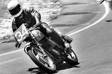
Seen in '39

What is all this leading up to? I will tell you. Some time ago I became involved in an argument anent spring frames and, being obstinate by nature, searched the Patents files to, prove my point. By accident I came across a specification for rear suspension registered in the joint names of Veloce Ltd., and Phillip Irving. There was something reminiscent about the drawing attached to the description which puzzled me for a minute or so until the penny dropped-I'd seen a similar coil spring device on F. J. Binder's Velocette in the Island during 1939 T.T. Race week. Enter the detective atmosphere ! Hot on the trail, a little more research brought to light two more patents taken out in the same names and dealing with the same subject.
Obviously, something had to be done about this. A letter to Veloce, Ltd., produced a most courteous invitation to visit the factory and to test the model. Thus it came about that, one dampish day recently, I listened to Phil Irving describing the many good points in the ingenious design and watched him demonstrate the ease with which the springing can be adjusted and if necessary, dismantled.
Patent No. 1 deals with this matter of adjustability, the basic idea being to provide a suspension system
instantaneously adaptable to widely varying loads. As with most good ideas, the method is simple in the extreme. The rear wheel is mounted in a swinging fork. Hinged to each fork end, slightly above and forward of the wheel spindle, is a straightforward telescopic plunger surrounded by a stout coil spring. And now comes the cunning part-the top end of each plunger is mounted on a transverse rod passing through slots formed in the rear frame member and the rod can be, locked by handwheels in a number of positions ranging from the nearly vertical to one where the spring members are inclined forward considerably.
Seen in '39


What is all this leading up to? I will tell you. Some time ago I became involved in an argument anent spring frames and, being obstinate by nature, searched the Patents files to, prove my point. By accident I came across a specification for rear suspension registered in the joint names of Veloce Ltd., and Phillip Irving. There was something reminiscent about the drawing attached to the description which puzzled me for a minute or so until the penny dropped-I'd seen a similar coil spring device on F. J. Binder's Velocette in the Island during 1939 T.T. Race week. Enter the detective atmosphere ! Hot on the trail, a little more research brought to light two more patents taken out in the same names and dealing with the same subject.
Obviously, something had to be done about this. A letter to Veloce, Ltd., produced a most courteous invitation to visit the factory and to test the model. Thus it came about that, one dampish day recently, I listened to Phil Irving describing the many good points in the ingenious design and watched him demonstrate the ease with which the springing can be adjusted and if necessary, dismantled.
Patent No. 1 deals with this matter of adjustability, the basic idea being to provide a suspension system
instantaneously adaptable to widely varying loads. As with most good ideas, the method is simple in the extreme. The rear wheel is mounted in a swinging fork. Hinged to each fork end, slightly above and forward of the wheel spindle, is a straightforward telescopic plunger surrounded by a stout coil spring. And now comes the cunning part-the top end of each plunger is mounted on a transverse rod passing through slots formed in the rear frame member and the rod can be, locked by handwheels in a number of positions ranging from the nearly vertical to one where the spring members are inclined forward considerably.

Variable Resistance
In the upright position the springs exert their greatest resistance to wheel movement; in the forward position the freedom of wheel movement is increased. Intermediate positions, of course, permit of settings between these extremes. The curved slots are so plotted that virtually no variation takes place in the position of the main frame relative to the rear wheel, thus the steering remains unaffected by variations in setting. Incidentally, a later design provides for arcuate slots which make the transverse bar selflocking at the peaks of the curves.
In the upright position the springs exert their greatest resistance to wheel movement; in the forward position the freedom of wheel movement is increased.
 Intermediate positions, of course, permit of settings between these extremes. The curved slots are so plotted that virtually no variation takes place in the position of the main frame relative to the rear wheel, thus the steering remains unaffected by variations in setting. Incidentally, a later design provides for arcuate slots which make the transverse bar selflocking at the peaks of the curves.
Chain Adjustment
Patent No. 2 is so simple as to make anyone who sees it chuckle-and then go into a quiet corner and kick himself for not thinking of it first! It permits of rear chain adjustment without the slightest fear of the rear wheel getting out of line. Method? Simple, my dear Watson! The pivot upon which the rear fork swings is mounted eccentrically on its bolt; thus, partial rotation of the eccentric slides the complete fork slightly forward or backward, leaving the wheel spindle location undisturbed.
Patent No. 2 is so simple as to make anyone who sees it chuckle-and then go into a quiet corner and kick himself for not thinking of it first! It permits of rear chain adjustment without the slightest fear of the rear wheel getting out of line. Method? Simple, my dear Watson! The pivot upon which the rear fork swings is mounted eccentrically on its bolt; thus, partial rotation of the eccentric slides the complete fork slightly forward or backward, leaving the wheel spindle location undisturbed.
This eccentric plot has been applied to dynamo chain adjustment for some years and the primary chain adjustment on the Lea-Francis consisted of a circular gearbox with the shell offset in relation to the mainshaft, but it has been left to Messrs. Veloce and Irving to apply such a common-sense adjustment to the secondary chain.
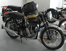
Patent No. 3 provided the real eye-opener, being none other than the employment of a stressed-skin rear frame, in which suitably formed sheet metal replaces the tubular construction usually associated with the job of supporting the rear wheel and accommodating road shocks. As the photographs and drawings show, a single sheet of metal, bolted to the tubular centre frame at several points, acts as mudguard and support for the top ends of the spring plungers and base for pillion seat and saddle. The rear half of this member can be arranged to hinge, thus giving access to the rear wheel, whilst toolbox, battery carrier and other " cupboard space " can also be combined in the one pressing.
Patent No. 3 provided the real eye-opener, being none other than the employment of a stressed-skin rear frame, in which suitably formed sheet metal replaces the tubular construction usually associated with the job of supporting the rear wheel and accommodating road shocks. As the photographs and drawings show, a single sheet of metal, bolted to the tubular centre frame at several points, acts as mudguard and support for the top ends of the spring plungers and base for pillion seat and saddle. The rear half of this member can be arranged to hinge, thus giving access to the rear wheel, whilst toolbox, battery carrier and other " cupboard space " can also be combined in the one pressing.

The Friction Dampers
Another particularly interesting detail consists of the built-in friction damper incorporated in each spring plunger. The male member carries two Ferodo rings standing proud of suitable supporting steel collars which are firmly attached to the plunger. These act as guide bearings. Placed between the collars are two semicircular pieces of Ferodo, forced outwards and into contact with the female outer sleeve by a circular clock spring, which exert a predetermined pressure. The assembly is designed to run dry indeed, lubricant obviously has a deleterious effect on brake lining material-and has proved entirely satisfactory and devoid of wear.
Another particularly interesting detail consists of the built-in friction damper incorporated in each spring plunger. The male member carries two Ferodo rings standing proud of suitable supporting steel collars which are firmly attached to the plunger. These act as guide bearings. Placed between the collars are two semicircular pieces of Ferodo, forced outwards and into contact with the female outer sleeve by a circular clock spring, which exert a predetermined pressure. The assembly is designed to run dry indeed, lubricant obviously has a deleterious effect on brake lining material-and has proved entirely satisfactory and devoid of wear.

Proved
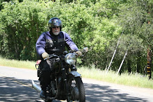
Lest that last statement be taken with a grain of salt, may I add that Irving demonstrated the test machine, which has covered over 90,000 miles without any replacement in the suspension system, when I gained ocular proof that no wear has taken place over this great mileage. As Phil emphasized the fact in no uncertain terms, I had better state at this stage that the machine under discussion is, in his own words, " A lash-up intended to prove principles and not to win beauty prizes." When experimental work is completed and a production prototype is built, the appearance will probably be very different.
Lash-up or no lash-up, a road test soon proved the efficiency of the design. For purposes of comparison, the experimental " springer " and a standard rigid-frame model were ridden out by Phil and myself to a vile, unmade road on a housing estate, the surface of which deteriorated rapidly from uneven cobbles to cobbles with gaps and then to gaps with exposed manhole covers and other aids to aviation. I first tried the " springer " with the plungers in the forward, or most resilient, position and then had a second run with the plungers in the back notch. Even in the former case there was no " bottoming," but it was surprising to note what a difference was made to the swinging fork action by such a comparatively small variation in the plunger angle.
On Rough Going
Having several times galloped down the stretch at some 25 m.p.h. on the spring heel, meanwhile deliberately aiming at the worst obstructions, I nearly cast myself off when I attempted the same gait on the rigid model. Hitting the edge of a particularly dreadful pothole a resounding clout-it seemed more like a pitshaft-I felt the back wheel rise to such an extent that I thought for a split second I was going over the bars. The incident must have looked funny to Phil, riding along behind me, as he said something about " What a pity the photographer is not with us." So far as I was concerned, however, it taught me a lesson; after that I did what one usually does with a rigid frame in such conditions picked out a crooked, but more comfortable, path and took things considerably slower.
Manfully hiding any qualms I might have, I then mounted on the pillion device behind Phil. This, I thought, was to be the acid test of the springing, to say nothing of my courage! The result was even more impressive than when I had been in the saddle. I weigh, roughly, 15 stone, but only once did the springing " bottom " over the aforesaid pitshaft and even then I suffered no discomfort and there was no subsequent " life on the ocean wave " rocking reaction such as might have been expected.
Again it took the rigid frame to demonstrate just how efficient is the spring-heel design. Even following the excrescence-dodging path at a much reduced speed the bumping was so severe that the headlamp front fell off and I acquired a severe " headache " in reverse. The demonstration was very convincing, my only regret being that I failed to take Phil on the pillion of the rigid-frame model after the shaking he gave me!
Convinced
Some spring frames are good, others are all " spring " and others might be solid for all the benefit obtained. The Veloce type tested definitely qualifies for the first category. It has all the perfect steering qualities of the maker's excellent rigid frame, combined with first-rate comfort for rider and passenger. The lateral rigidity of the wide pivot bearing and the deep stressed-skin rear frame member must be ample for the purpose, as there was no visible trace of shake and certainly none could be felt even over rutted three-ply lanes. And let it not be overlooked that more than 90,000 miles had been covered on this machine since it was put into commission in the autumn of 1938.
Regarding ease of maintenance, the problem seems to have been solved by giving the rider no maintenance to do. The bottom bearing in each spring leg consists of a floating Oilite bronze bush, which has proved ideal for the niggling semi-rotary motion to which it is subjected. The fork pivot bearing is equipped with a simple grease nipple with suitable passages in the member leading to the bronze bushes, whilst, as has been previously stated, the Ferodo guide-cum-damper assembly runs dry.
Assembling
The assembly of the spring leg is very simple. First, the bottom Ferodo guide, with its steel collar, slips down to a shoulder formed on the inner member. Next, the semi-circular pieces of Ferodo and the little clock spring are nipped into position with a piece of string. Then the top Ferodo-and-steel collar is screwed on. Next, the spring is screwed on to the helix on the plunger and, finally, the sheath is slipped over the plunger and inside the spring. As the sheath slides over the damper segments the string is removed and then the sheath is given a half turn so that its external bayonet catch engages with the top spring coil. That's all!
To sum up, as an attempt to provide a suspension system instantly adjustable to solo or pillion loads, allied to ease of maintenance and long life, the experiment appears to be a complete
success. I am very glad I found that patent specification. There is always a thrill in testing something new, and more particularly when the something new indicates that war-time conditions have not been allowed to cry " Halt " to post-war progress.
Lash-up or no lash-up, a road test soon proved the efficiency of the design. For purposes of comparison, the experimental " springer " and a standard rigid-frame model were ridden out by Phil and myself to a vile, unmade road on a housing estate, the surface of which deteriorated rapidly from uneven cobbles to cobbles with gaps and then to gaps with exposed manhole covers and other aids to aviation. I first tried the " springer " with the plungers in the forward, or most resilient, position and then had a second run with the plungers in the back notch. Even in the former case there was no " bottoming," but it was surprising to note what a difference was made to the swinging fork action by such a comparatively small variation in the plunger angle.
On Rough Going

Having several times galloped down the stretch at some 25 m.p.h. on the spring heel, meanwhile deliberately aiming at the worst obstructions, I nearly cast myself off when I attempted the same gait on the rigid model. Hitting the edge of a particularly dreadful pothole a resounding clout-it seemed more like a pitshaft-I felt the back wheel rise to such an extent that I thought for a split second I was going over the bars. The incident must have looked funny to Phil, riding along behind me, as he said something about " What a pity the photographer is not with us." So far as I was concerned, however, it taught me a lesson; after that I did what one usually does with a rigid frame in such conditions picked out a crooked, but more comfortable, path and took things considerably slower.
Manfully hiding any qualms I might have, I then mounted on the pillion device behind Phil. This, I thought, was to be the acid test of the springing, to say nothing of my courage! The result was even more impressive than when I had been in the saddle. I weigh, roughly, 15 stone, but only once did the springing " bottom " over the aforesaid pitshaft and even then I suffered no discomfort and there was no subsequent " life on the ocean wave " rocking reaction such as might have been expected.
Again it took the rigid frame to demonstrate just how efficient is the spring-heel design. Even following the excrescence-dodging path at a much reduced speed the bumping was so severe that the headlamp front fell off and I acquired a severe " headache " in reverse. The demonstration was very convincing, my only regret being that I failed to take Phil on the pillion of the rigid-frame model after the shaking he gave me!

Convinced
Some spring frames are good, others are all " spring " and others might be solid for all the benefit obtained. The Veloce type tested definitely qualifies for the first category. It has all the perfect steering qualities of the maker's excellent rigid frame, combined with first-rate comfort for rider and passenger. The lateral rigidity of the wide pivot bearing and the deep stressed-skin rear frame member must be ample for the purpose, as there was no visible trace of shake and certainly none could be felt even over rutted three-ply lanes. And let it not be overlooked that more than 90,000 miles had been covered on this machine since it was put into commission in the autumn of 1938.
Regarding ease of maintenance, the problem seems to have been solved by giving the rider no maintenance to do. The bottom bearing in each spring leg consists of a floating Oilite bronze bush, which has proved ideal for the niggling semi-rotary motion to which it is subjected. The fork pivot bearing is equipped with a simple grease nipple with suitable passages in the member leading to the bronze bushes, whilst, as has been previously stated, the Ferodo guide-cum-damper assembly runs dry.
Assembling
The assembly of the spring leg is very simple. First, the bottom Ferodo guide, with its steel collar, slips down to a shoulder formed on the inner member. Next, the semi-circular pieces of Ferodo and the little clock spring are nipped into position with a piece of string. Then the top Ferodo-and-steel collar is screwed on. Next, the spring is screwed on to the helix on the plunger and, finally, the sheath is slipped over the plunger and inside the spring. As the sheath slides over the damper segments the string is removed and then the sheath is given a half turn so that its external bayonet catch engages with the top spring coil. That's all!
To sum up, as an attempt to provide a suspension system instantly adjustable to solo or pillion loads, allied to ease of maintenance and long life, the experiment appears to be a complete
success. I am very glad I found that patent specification. There is always a thrill in testing something new, and more particularly when the something new indicates that war-time conditions have not been allowed to cry " Halt " to post-war progress.


No comments:
Post a Comment